

Retrofitting & Rehabilitation
Rehabilitation & Retrofitting
NeXHS provides rehabilitation and retrofitting solutions for wind turbine structures, leveraging its expertise in structural design and engineering to assess damage, identify root causes and extend structural service life.
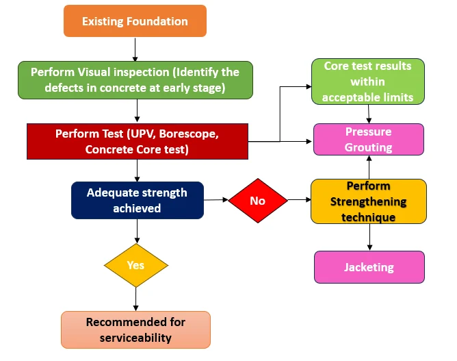
Our approach includes detailed site investigations and condition assessments, supported by the evaluation of NDT results, concrete core analysis, borescope inspections and other diagnostic studies. Advanced Finite Element Analysis (FEA) is used to assess structural behaviour and determine the extent and impact of deterioration.
Based on these findings, NeXHS develops site-specific, optimised retrofitting solutions aimed at restoring structural performance, improving reliability and supporting safe continued operation.
Various problems of the WTG Foundation
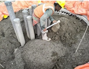
Spreading of completely dried concrete without proper compaction
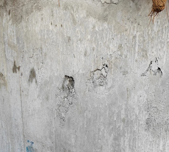
Cracking and Popouts on the surface of the concrete
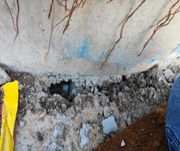
Delamination of Concrete in the Pedestal Zone
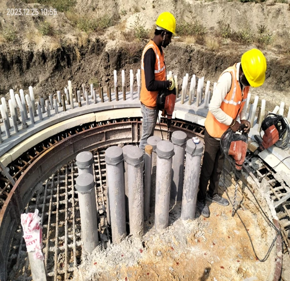
Exposed rebar in pedestal zone
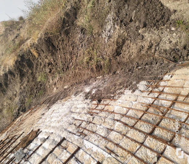
Exposed rebar in pedestal zone
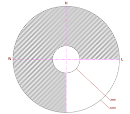
Cold Joint in different portion of raft
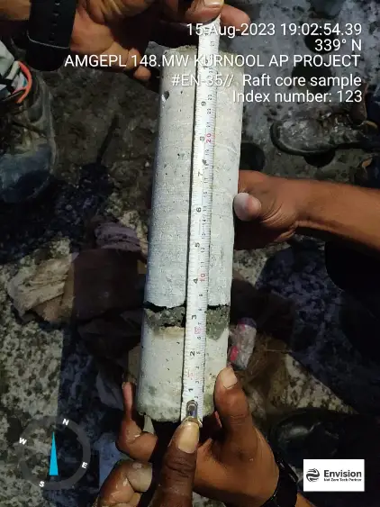
Core samples extracted from cold joint areas
Delamination of Concrete in the Pedestal Zone
Process of WTG Foundation
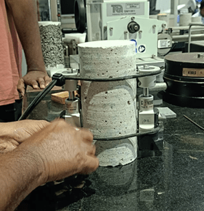
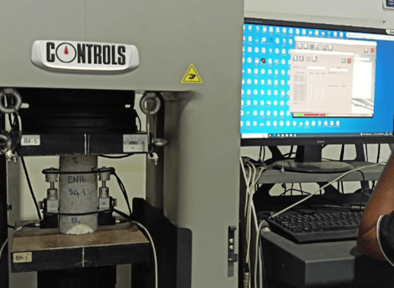
Determining the modulus of elasticity of concrete in compression by means of an extensometer
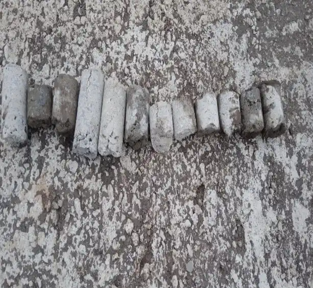
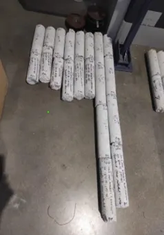
Core samples of foundations
Visual quality inspection work using a Borescope (After core drilling)
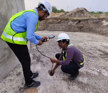
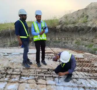
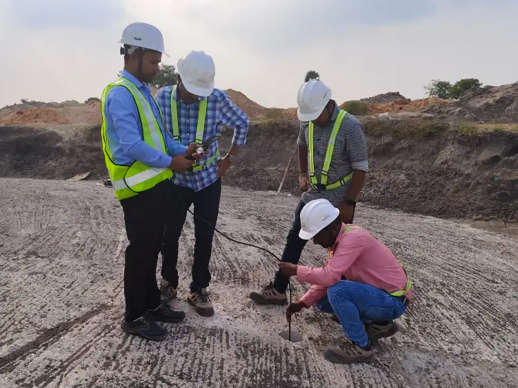
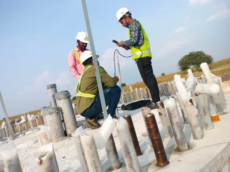
UPV
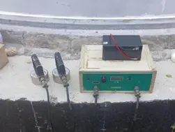
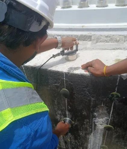
UPV equipment consists of a Generator that generates an electrical pulse, two transducers (transmitting and receiving transducers), an amplifier, and a time interval measuring device.
The approximate extent of imperfections like voids or low compaction needs to be determined by conducting UPV tests in the WTG locations, as the Elastic stiffness and mechanical strength properties have a direct influence on the velocity of the Ultrasonic pulse.
Pulse velocity is measured by placing the transducers on the same face, in both the WTG Concrete foundations (indirect or surface transmission). As per BS 1881, a minimum path length of 400mm for indirect transmission is recommended.
Steps for Pressure Grouting procedure of WTG Foundation
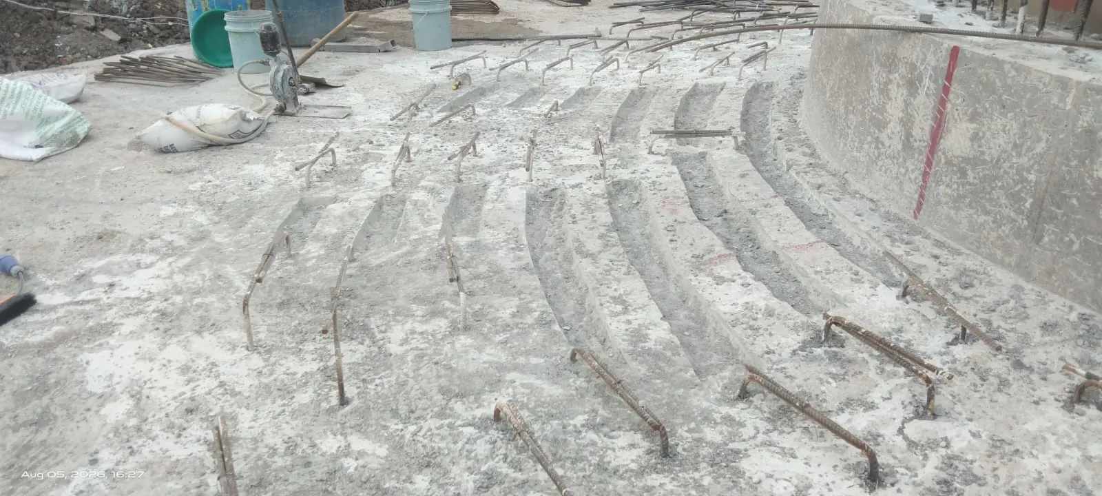
- Chipping of the pedestal
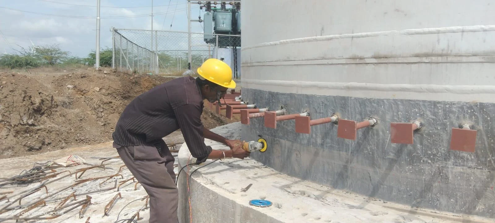
- Drilling in the raft region
- Vertical drilling in the pedestal region
- Rebar installation
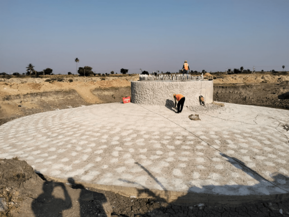
(a) Chipping of the pedestal
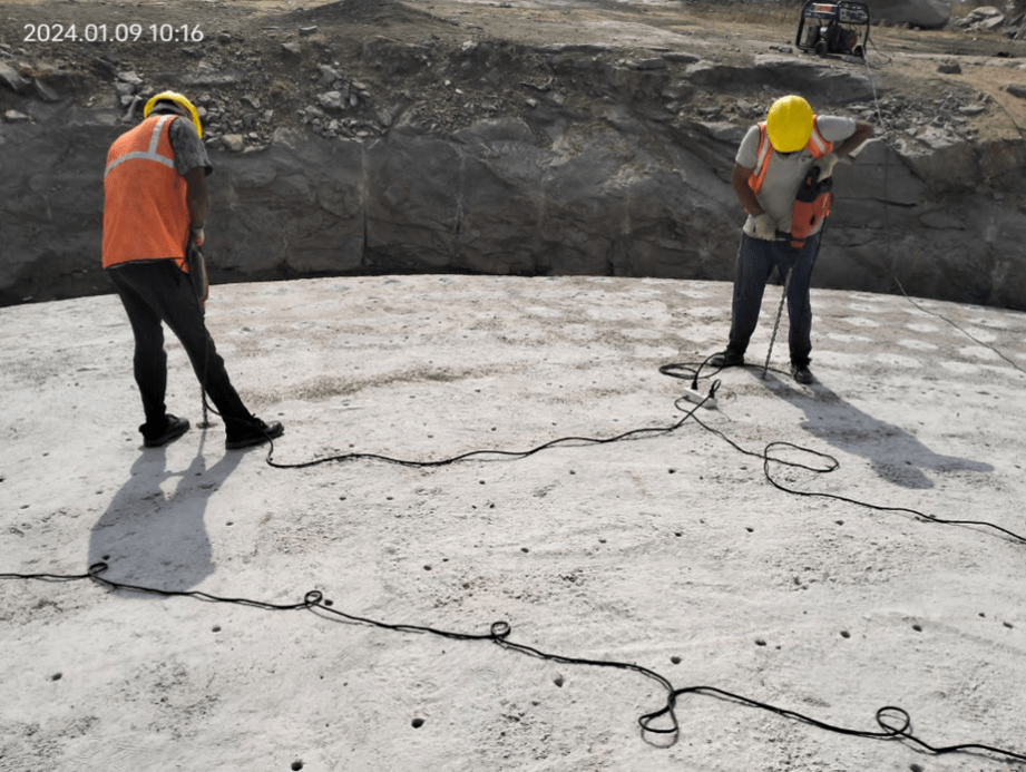
(b) Drilling in the raft region
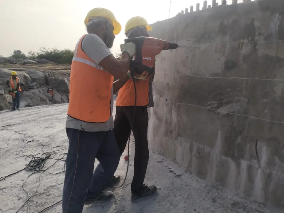
(c) Vertical drilling in the pedestal region
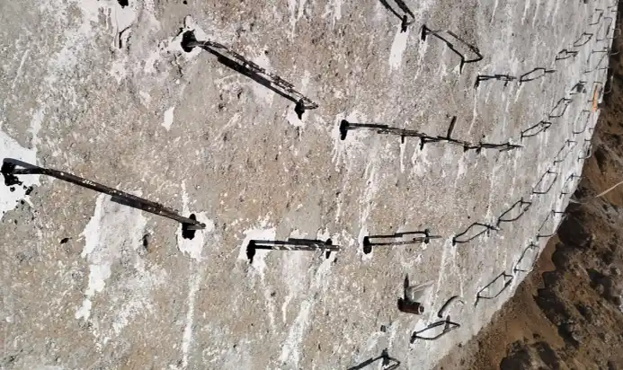
(d) Rebar installation
Case I
Project Overview :
• The foundation of the wind turbine was identified with cracks.
• Delay in the concreting of the slab and pedestal.
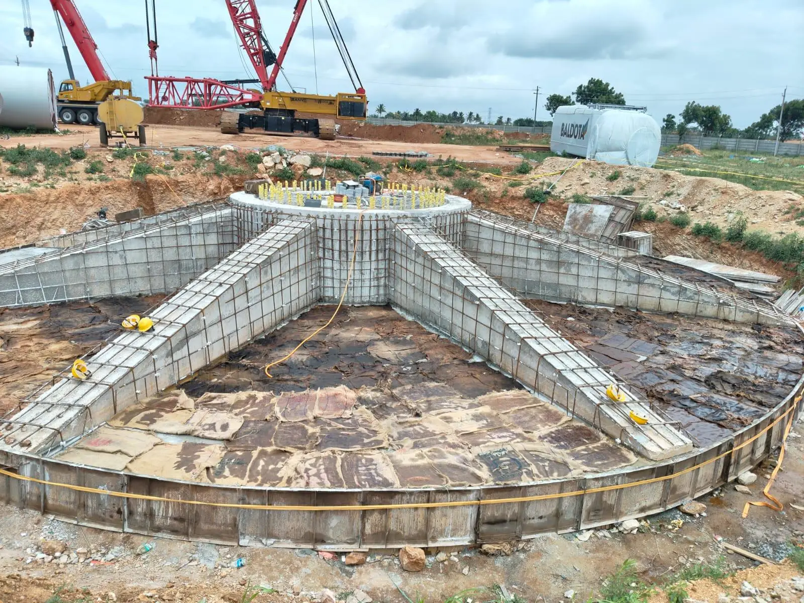
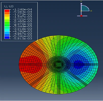
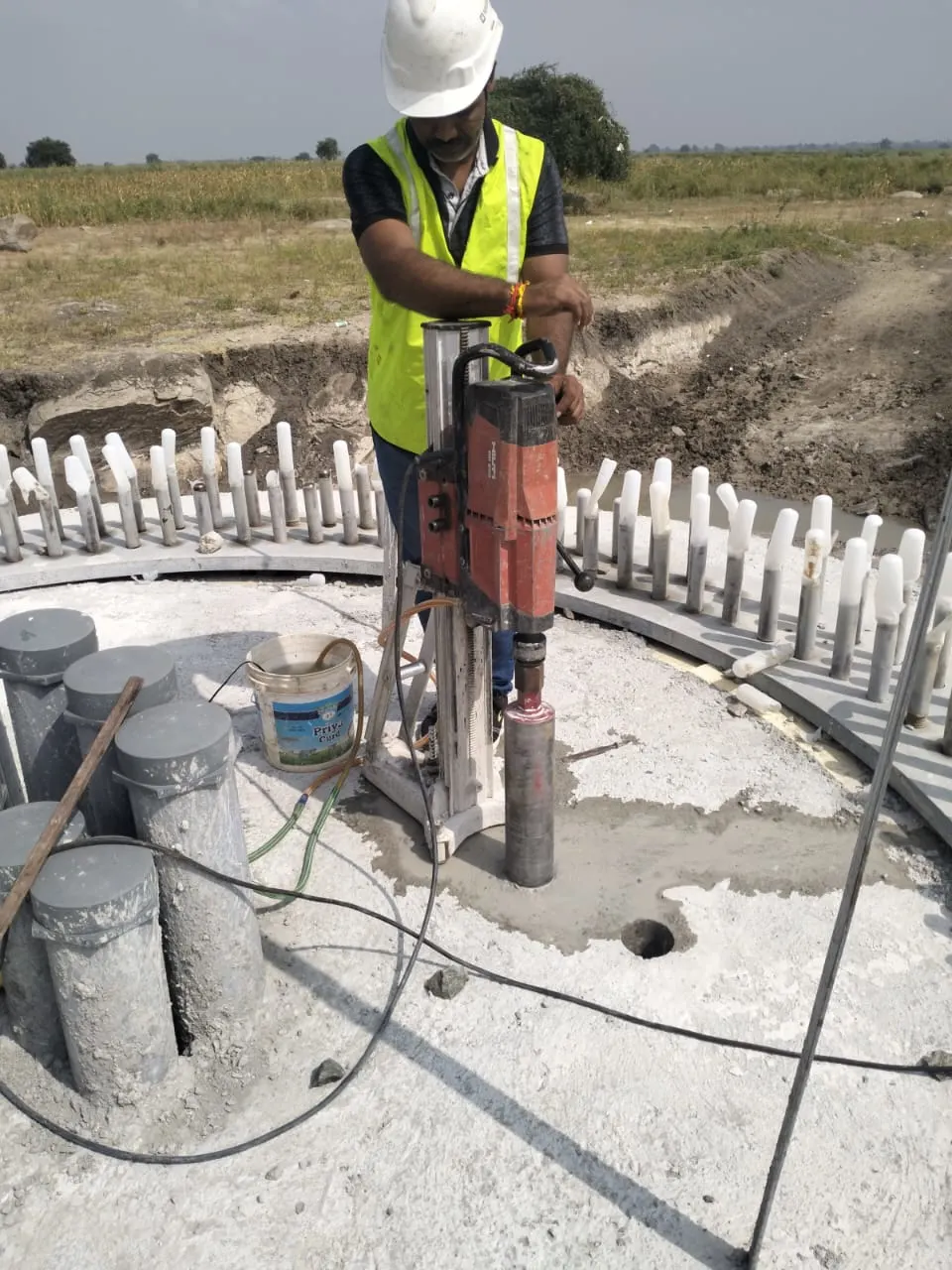
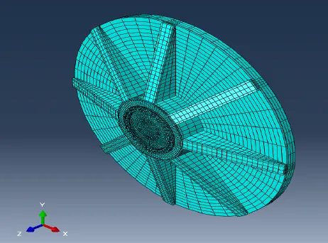
Conceptualisation of the Problem:
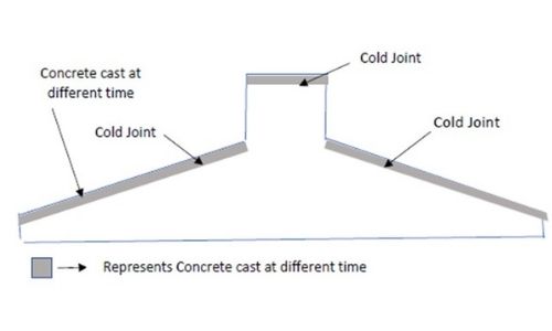
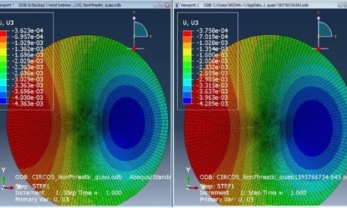
Cracks or cold joints were formed at the slab and pedestal region of the wind turbine foundation because the concrete was cast at different times. Analysis was carried out for the reduced properties of concrete by reducing the stiffness of the concrete.
Based on the results from the analysis the solutions were provided for the retrofitting.
Solution Provided by NeXHS:
To match with the stiffness criteria, introduction of studs along the circumference of the embedded can was proposed. Further, grouting was donein multiple places to increase the bonding between the existing concrete.
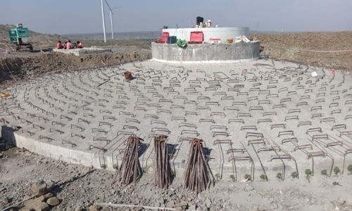
Reinforced concrete jacketing improves slab flexural & shear strength.
Case II
Project Overview :
The square foundation of the WTG tower was reported to have vibration which resulted in the loss of bond between the region of the embedded can and the underlying concrete area. NDT tests and bosrescopy were performed to evaluate the strength of the concrete.
Conceptualisation of the Problem:
Minor cracks were observed at the bottom portion, and it was inferred that the concrete at the bottom region of the foundation has lost contact with the embed can.
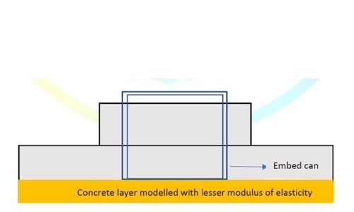
Due to the vibration, the concrete in the interface of the embedded can have reduced stiffness and strength.
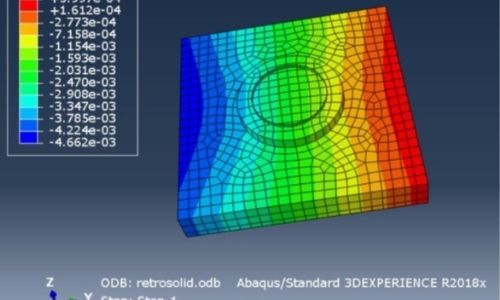
The bottom layer of concrete modelled with a reduced elasticity modulus
Solution Provided by NeXHS:
To match with the stiffness criteria,introduction of studs along the circumference of the embedded can was proposed. Further, grouting was donein multiple places to increase the bonding between the existing concrete.